

Miniature check valves control flow rate and prevent backflow. With cracking pressures from 0 – 2 bar, they suit a range of applications with different operating pressures. With forward and reverse flow options, Koenig check valves help OEM’s around the world manage fluid in advanced engineering applications.
Automotive manufacturers use Koenig check valves in fuel and braking systems, Aerospace engineers trust them in high pressure pumps, and Designers in fluid power use check valves in Hydraulic manifolds and cylinders.
This article covers the basic design guidelines you should follow when designing Koenig check valves into your application.
Wall thickness/distance from edge
Wall thickness and distance from edge must be considered when designing a Koenig check valve installation. Resultant strength, hydraulic pressure and temperature service conditions all require a minimum wall thickness for reliable performance.
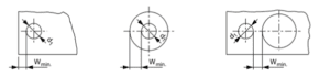
As radial expansion of the check valve occurs, securing the component in place, the base material plastically deforms. To ensure this deformation doesn’t interfere with the minimum wall thickness/distance from edge, you should use the following formula:
Wmin = Fmin x d1
Different base materials have different factor values (Fmin). See the table below for reference.
| Base material of installation | ||||
| ETG-100/44Mn28 AISI1144 | EN 1563: GJS-600-3 ASTM A536: 80-60-03 | AISI 303 EN 1.4305 X8CrNiS18-9 | EN 1563: GJS-450-10 ASTM A536: 65-45-12 | AICuMg1 / EN AW-2024-T3 AA: 2024 T4/T6 |
| Factor (Fmin) | ||||
| 0.4 | 0.5 | 0.5 | 0.8 | 0.5 |
Multiply your Fmin by d1 – the diameter of the hole that needs sealing.
This will give you the minimum wall thickness/distance from edge needed to ensure a reliable and safe check valve installation.
Roundness tolerance
For a miniature check valve to work effectively it must reliably prevent side leakage. This helps ensure reliable pressure performance and control of fluid through your application. To do this your channel needs to have a roundness tolerance of t= 0.05mm.
To achieve this roundness tolerance, you should use a double-lipped twist drill. It’s worth noting that better tolerances are needed in larger diameter holes. To reach these tolerances a triple-lipped twist drill is used.
Conicity of bore
Koenig check valves use the anchorage system to create a tight, leak proof seal. To make sure the anchorage system works properly the bore must be in accordance with the dimensional sheets.
The bore lead-in can be 0.25 x d1 (check valve diameter) as this area doesn’t affect the anchorage function.
Koenig Design Guidelines: How to Design Koenig Check Valve Installations
Koenig Check Valves control flow rate and prevent backflow. With cracking pressures from 0 – 2 bar, they suit a range of applications with different operating pressures. With forward and reverse flow options, Koenig check valves help OEM’s around the world manage fluid in advanced engineering applications.
Automotive manufactures use Koenig check valves in fuel and braking systems, Aerospace engineers trust them in high pressure pumps, and Designers in fluid power use check valves in Hydraulic manifolds and cylinders.
This article covers the basic design guidelines you should follow when designing Koenig check valves into your application.
Wall thickness/distance from edge
Wall thickness and distance from edge must be considered when designing a Koenig check valve installation. Resultant strength, hydraulic pressure and temperature service conditions all require a minimum wall thickness for reliable performance.
As radial expansion of the check valve occurs, securing the component in place, the base material plastically deforms. To ensure this deformation doesn’t interfere with the minimum wall thickness/distance from edge, you should use the following formula:
Wmin = Fmin x d1
Different base materials have different factor values (Fmin). See the table below for reference.
|
Base material of installation |
||||
| ETG-100/44Mn28
AISI1144 |
EN 1563: GJS-600-3
ASTM A536: 80-60-03 |
AISI 303
EN 1.4305 X8CrNiS18-9 |
EN 1563: GJS-450-10
ASTM A536: 65-45-12 |
AICuMg1 /
EN AW-2024-T3 AA: 2024 T4/T6 |
|
Factor (Fmin) |
||||
| 0.4 | 0.5 | 0.5 | 0.8 | 0.5 |
Multiply your Fmin by d1 – the diameter of the hole that needs sealing.
This will give you the minimum wall thickness/distance from edge needed to ensure a reliable and safe check valve installation.
Roundness tolerance
For a check valve to work effectively it must reliably prevent side leakage. This helps ensure reliable pressure performance and control of fluid through your application. To do this your channel needs to have a roundness tolerance of t= 0.05mm.
To achieve this roundness tolerance, you should use a double-lipped twist drill. It’s worth noting that better tolerances are needed in larger diameter holes. To reach these tolerances a triple-lipped twist drill is used.
Conicity of bore
Koenig check valves use the anchorage system to create a tight, leak proof seal. To make sure the anchorage system works properly the bore must be in accordance with the dimensional sheets.
The bore lead-in can be 0.25 x d1 (check valve diameter) as this area doesn’t affect the anchorage function.


